
")
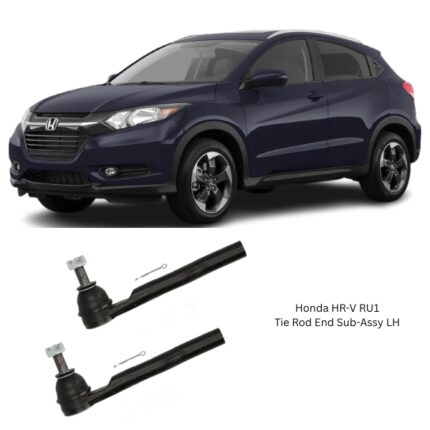
Get Honda HR-V RU1 Tie Rod End Sub-Assy LH 53560-T7A-003 in Kenya
The Tie Rod End Sub-Assembly LH (Left-Hand Side) is a critical component of the steering linkage system in vehicles equipped with rack-and-pinion or parallelogram steering systems. It functions as the outermost segment of the tie rod, linking the steering rack or center link to the steering knuckle on the left-hand wheel. Its primary role is to translate the rotational movement of the steering wheel into lateral movement of the wheels, enabling precise directional control of the vehicle.
Despite its relatively small size, the tie rod end plays an essential role in maintaining proper wheel alignment, handling responsiveness, tire life, and overall driving safety. Any failure or deterioration in the tie rod end can severely affect the steering system and vehicle stability.
Function and Role in the Steering System
The Tie Rod End LH Sub-Assembly connects the left side of the steering linkage to the suspension and wheel hub assembly. It consists of a ball joint that allows multi-axis rotation and articulation, enabling the wheels to respond to both steering input and suspension movement.
Key Functional Roles:
-
Transfers Steering Input to the Wheel
When the driver turns the steering wheel, the steering rack or center link moves laterally. The tie rod end connects to this and transmits the motion directly to the wheel hub via the knuckle. -
Allows Suspension Movement
Since the wheel moves up and down over bumps and dips, the tie rod end’s ball joint accommodates this vertical travel without disrupting steering geometry. -
Maintains Alignment Angles
Properly functioning tie rod ends are crucial to maintaining toe angle and overall front-end alignment, which directly affects tire wear and steering precision. -
Supports Load Distribution
While not a load-bearing suspension component, tie rod ends withstand significant lateral forces during cornering, braking, and rough road travel.
Construction and Design
The Tie Rod End Sub-Assembly is engineered for high durability, smooth articulation, and resistance to mechanical and environmental wear. It is usually a compact, self-contained unit designed for direct installation onto the steering linkage or inner tie rod.
Primary Components:
-
Ball Stud
A spherical-headed, high-strength steel stud that fits into a matching socket, allowing for rotational and angular movement. The threaded end connects to the steering knuckle. -
Socket Housing
A forged or cast metal casing that holds the ball stud. It is internally lined with a bearing surface, typically made of polymer or metal, to reduce friction and wear. -
Dust Boot
A rubber or synthetic boot that seals the joint from external contaminants like water, dirt, and road salt. It also retains lubrication within the socket. -
Threaded Adjusting Sleeve or Shaft End
Provides fine adjustment for toe alignment. This allows the technician to lengthen or shorten the tie rod during wheel alignment procedures. -
Grease Fitting (Optional)
Some designs include a zerk fitting for periodic lubrication, although many modern assemblies are sealed-for-life.
Material and Durability
Given the extreme forces encountered during steering and road interaction, tie rod ends must be constructed from high-strength materials:
-
Ball Stud: Case-hardened steel or chromoly steel for strength and wear resistance.
-
Socket Housing: Forged steel or heat-treated cast iron for structural integrity.
-
Bearings: Synthetic polymer or PTFE liners for low-friction operation.
-
Dust Boot: Thermoplastic elastomer or nitrile rubber to withstand heat, chemicals, and physical abuse.
Some advanced designs include corrosion-resistant coatings such as zinc plating or phosphate treatments for enhanced service life in harsh environments.
Symptoms of a Worn or Failing Tie Rod End (LH)
Because tie rod ends are exposed to constant movement and environmental contaminants, they are subject to gradual wear over time. Failure can be dangerous, as it directly impacts steering control.
Common Signs of a Failing Left-Hand Tie Rod End:
-
Steering Play or Looseness
Excessive free play in the steering wheel often signals internal wear in the tie rod end. -
Clunking or Knocking Noise
Particularly noticeable when turning the steering wheel or driving over rough terrain. -
Uneven or Rapid Tire Wear
Due to misaligned toe angle caused by a worn or loose tie rod end. -
Pulling to One Side
Vehicle may drift left or right when driving straight. -
Steering Wheel Vibration
Especially noticeable at highway speeds, caused by instability in the steering linkage. -
Visual Inspection Issues
A torn or leaking dust boot, corrosion, or visible looseness in the joint.
Inspection and Diagnosis
Technicians typically check tie rod ends during routine suspension or alignment inspections.
-
Lift the Vehicle: Unload the front suspension.
-
Manual Movement Test: Wiggle the wheel laterally and vertically; excessive movement may indicate tie rod play.
-
Use of Pry Bar: Apply force to detect any looseness in the joint.
-
Visual Check: Look for rust, torn boots, or grease leakage.
Installation and Replacement
Replacement of a Tie Rod End Sub-Assy LH is relatively straightforward but must be done with care to preserve alignment geometry.
General Procedure:
-
Raise the Vehicle and Secure It
Use jack stands and wheel chocks for safety. -
Remove Front Wheel (Left Side)
For full access to the tie rod end and steering knuckle. -
Loosen Jam Nut on Inner Tie Rod
This locks the outer tie rod in place. -
Remove Tie Rod End from Steering Knuckle
Use a tie rod puller or separator to disconnect the tapered stud. -
Unscrew the Old Tie Rod End
Count the number of turns to preserve approximate alignment. -
Install New Tie Rod End
Thread it onto the inner tie rod using the same number of turns. -
Reconnect to Knuckle and Tighten
Torque to manufacturer specifications and install a new cotter pin if applicable. -
Realign the Vehicle
A professional wheel alignment is necessary after replacement to ensure optimal steering and tire wear.
Maintenance Tips
-
Inspect Regularly
During oil changes or tire rotations. -
Monitor Boot Condition
Replace the joint immediately if the boot is damaged or leaking. -
Lubricate if Serviceable
Grease the joint periodically if a zerk fitting is provided. -
Avoid Off-Road Impacts
Large potholes, curbs, or off-road obstacles can accelerate wear or damage the joint.
Follow us on Facebook for more parts.
Reviews
Clear filtersThere are no reviews yet.