

")
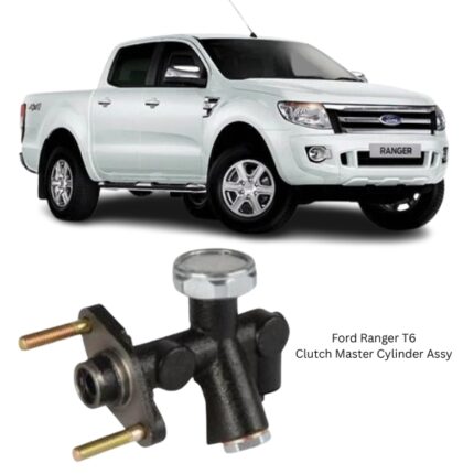
Get Ford Ranger T6 Clutch Master Cylinder Assy YB12221-00A32 in Kenya
The Clutch Master Cylinder Assembly is a core component of hydraulic clutch systems, tasked with initiating the transfer of force from the driver’s foot to the clutch release mechanism. Operating as the first hydraulic actuator in the clutch circuit, it converts mechanical pedal pressure into hydraulic fluid movement, which is essential for smooth clutch disengagement and gear changes in manual transmission systems.
By ensuring precise control of the clutch mechanism, the master cylinder plays a vital role in vehicle drivability, shift timing, and clutch wear management. It interacts directly with the clutch pedal and delivers fluid through the hydraulic line to the slave cylinder, completing a closed-loop system that must remain sealed, responsive, and consistent under a variety of temperature and pressure conditions.
Function and Working Principle
The clutch master cylinder operates by using a piston inside a sealed fluid chamber. When the clutch pedal is depressed, the piston is pushed forward inside the master cylinder bore. This motion pressurizes the hydraulic brake fluid or clutch fluid within the cylinder, forcing it through a high-pressure hose toward the clutch slave cylinder.
The fluid movement activates the slave cylinder, which then pushes on the clutch fork or bearing to disengage the clutch disc from the flywheel. Once the clutch pedal is released, the piston inside the master cylinder returns to its original position with the aid of an internal spring. This creates negative pressure that allows fluid to flow back into the master cylinder’s reservoir and enables the clutch system to re-engage the drivetrain.
This precise hydraulic action makes gear shifts smooth and enables clutch modulation, particularly important in low-speed driving, hill starts, and when launching from a stop.
Main Components
A typical clutch master cylinder assembly consists of the following elements:
-
Cylinder Body: Made from cast aluminum, cast iron, or reinforced polymer, it houses all internal components and connects to the clutch pedal via a push rod.
-
Internal Piston: A tightly machined rod that slides through the bore of the cylinder, generating pressure on the fluid when the clutch is engaged.
-
Primary and Secondary Seals: Rubber or synthetic elastomer seals that prevent internal leaks and maintain system pressure.
-
Return Spring: Ensures the piston retracts to its rest position once pressure is released.
-
Push Rod and Clevis Assembly: Links the clutch pedal to the piston, allowing mechanical force to be translated into hydraulic action.
-
Fluid Reservoir: Stores hydraulic fluid, typically mounted on top of the master cylinder or remotely via a hose.
-
Outlet Port: Connects to the hydraulic line leading to the slave cylinder, ensuring fluid movement with each pedal action.
-
Bleeder Valve (in some designs): Allows air removal from the hydraulic system during servicing.
Materials and Durability
The materials used in manufacturing clutch master cylinders must be capable of withstanding repetitive force, heat, and exposure to brake fluid—an aggressive, high-pressure medium. Typical material choices include:
-
Anodized aluminum: Lightweight and corrosion-resistant, commonly used for the body and mounting flange.
-
High-carbon steel: Used for pistons and rods requiring additional strength and durability.
-
EPDM or Viton rubber: Employed in internal seals for chemical and thermal resistance.
-
Plastic or composite reservoirs: Molded for durability and transparency to aid in visual fluid level inspections.
These materials are chosen for longevity, compatibility with brake fluid, and ability to endure the high-cycle, high-pressure demands of daily clutch operation.
Types of Clutch Master Cylinders
Clutch master cylinders can vary slightly in design depending on the layout of the clutch system. Common types include:
-
Integral Reservoir Type:
-
The fluid reservoir is built directly into the master cylinder body.
-
Easier to install and more compact.
-
-
Remote Reservoir Type:
-
The reservoir is connected via a hose and mounted separately.
-
Allows for more flexibility in cramped engine compartments.
-
-
Straight Bore and Stepped Bore Designs:
-
Straight bore: Consistent internal diameter for uniform pressure generation.
-
Stepped bore: Two internal diameters to optimize fluid delivery and pedal feel.
-
Operation and Hydraulic Control
The clutch master cylinder plays a crucial role in maintaining pedal feel, actuation timing, and system response. Any inconsistencies in master cylinder performance can directly affect:
-
Clutch engagement point
-
Clutch pedal resistance
-
Transmission synchrony
-
Drivetrain smoothness
Its job is to ensure that every depression of the clutch pedal results in an equal and predictable amount of fluid movement—without delay, fluid loss, or inconsistent pressure.
In systems designed with load compensation or delay valves, the master cylinder may also play a part in gradually engaging the clutch to minimize shock loads on the drivetrain, improving overall mechanical harmony.
Installation Process
Replacing or installing a clutch master cylinder typically involves the following steps:
-
Accessing the master cylinder by removing relevant covers or components near the firewall or pedal area.
-
Disconnecting the clutch pedal linkage, usually via a clevis pin or push rod connection.
-
Removing the hydraulic line from the outlet port and draining any residual fluid.
-
Unbolting the master cylinder from the firewall or mounting bracket.
-
Installing the new unit, aligning it precisely to avoid push rod misalignment.
-
Refilling the fluid reservoir with the correct hydraulic fluid (commonly DOT3 or DOT4).
-
Bleeding the system to remove air, using either manual or pressure methods.
-
Testing clutch pedal travel and engagement consistency before driving.
In dual master cylinder systems or systems with a shared reservoir (for brakes and clutch), care must be taken not to introduce air or contaminants during replacement.
Symptoms of Failure
A failing clutch master cylinder can show several operational symptoms that affect drivability:
-
Soft or spongy clutch pedal
-
Difficulty engaging or shifting gears
-
Fluid leaks around the cylinder body or firewall
-
Low fluid level in the reservoir despite no visible leaks
-
Delayed clutch engagement or grinding gears
-
Pedal sticking or not returning fully
Internal seal failure, bore scoring, or air ingress are common causes of poor performance. Early diagnosis and replacement are essential to prevent damage to the slave cylinder and transmission.
Maintenance and Lifespan
While designed for long-term use, clutch master cylinders should be periodically inspected:
-
When the clutch fluid is changed (typically every 2–3 years).
-
During clutch replacements or when the slave cylinder is serviced.
-
If the vehicle experiences fluid loss or erratic clutch behavior.
Proper maintenance includes checking fluid levels, inspecting for leaks, and bleeding the system if necessary. Using the manufacturer-specified fluid type is vital to prevent seal degradation and system failure.
Integration in the Hydraulic Clutch System
The clutch master cylinder doesn’t work in isolation. It forms the initiating end of a hydraulic loop that includes:
-
Clutch pedal
-
Push rod
-
Hydraulic line
-
Clutch slave cylinder
-
Release fork and bearing
Its performance must be coordinated with all these elements for the clutch system to operate smoothly. Any failure or delay at this initial stage can have cascading effects throughout the transmission interface.
Follow us on Facebook for more parts.
Reviews
Clear filtersThere are no reviews yet.